Home | Glossary | Resources | Help | Contact Us | Course Map
Archival Notice
This is an archive page that is no longer being updated. It may contain outdated information and links may no longer function as originally intended.
Ignition Systems
The cannon lock established the firearm as a tool for the individual soldier. The next firearm component to evolve was the lock or propellant ignition system. The logical step beyond the cannon lock was to place the match on the firearm instead of requiring the soldier to hold it with the other hand. The dangers of holding a lighted match while trying to pour gunpowder down the barrel are readily apparent.
Matchlocks
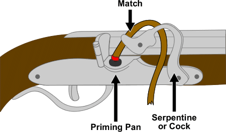
A metal rod, often in the shape of a gently curved S, held a match at one end and pivoted about the center. The opposite end from the match projected below the gun barrel where the operator could push or pull on it to cause the match to meet the touchhole. This class of firearms is called matchlocks. To allow the shooter to control and aim this firearm, the design of stock evolved to support the pivoting match holder. Illustrations of early matchlocks show the familiar form associated today with shoulder-fired small arms.
It is apparent that such a system would react slowly. To speed the firing process, designers conceived a spring-powered lock system. This system included the cock (the device that holds the match) and the trigger (a device to release the spring-loaded cock). To keep the firearm cocked, the shooter pulled back on the cock to store the springs energy and engage a notch in the cock with the trigger. A pull of the trigger released the cock a split-second later, and the match contacted the touchhole. Ultimately, the touchhole was moved to the side. A small pan was placed next to the touchhole to hold a charge of fine-grained priming powder, which improved ignition.
It is easy to imagine the difficulty of managing a matchlock in the heat of battle. The match could go out, requiring relighting with flint and steel (not an easy task in the days before disposable lighters). The system was practically useless in rainy weather. In spite of these serious shortcomings, cannon locks and matchlocks dominated the firearms industry for 150 years.
Wheel Locks
The next improvement was to eliminate the match, replacing it with a method that could generate fire on demand. Adapting household fire-starting implements, such as flint and steel, was the obvious choice. A flint creates a spark under conditions that would extinguish a match.
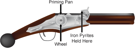
The first flint-fired arms were wheel locks from the early sixteenth century. History credits the wheel lock to Germany and/or Austria. A steel wheel with a serrated or knurled outer edge projected through the lock plate (the mounting plate for the ignition parts). The wheel was attached internally to a spiral spring and could be wound like a clock, storing energy in the wheel. A cock gripped a piece of flint (or iron pyrite) and could be lowered onto the wheel. Pulling the trigger momentarily released the wheel and lowered the flint on the spinning wheel, producing sparks. The sparks fell into a small pan containing a few grains of powder. A small hole, the vent, connected the exterior pan to the main powder charge in the barrel. When the powder in the pan fired, some of the fire traveled down the vent and initiated the main charge. The lighting mechanism of a modern cigarette lighter has corresponding parts; the wheel is turned manually and the lighter uses a fuel-soaked wick or butane jet in place of a powder pan.
Snaphaunce
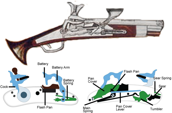
A few years after the introduction of the wheel lock, a simplified design combined flint firing from the wheel lock with the simplicity of the spring-actuated matchlock. Nearly every industrialized nation in Western Europe claimed its invention. The snaphaunce shared the side-mounted powder pan of later match locks and wheel locks. It used the basic spring cock and replaced the match holder with a flint holder. To provide a sparking surface for the flint, designers fitted a steel striking plate ( anvil) that pivoted over the side pan. When the cock fell against the anvils curved inner surface, it pushed the hinged anvil up and created a shower of sparks downward into the pan. For little more than the expense of fabricating a spring matchlock, nations could arm their troops with a simple, flint-fired musket or pistol.
The wheel lock proved to be significantly more reliable than the cannon lock and the matchlock. However, this progress incurred considerable financial cost. The locks were crafted by highly skilled artisans and required a level of precision not typically associated with manufacturing techniques of this historical period.
To reduce a firearms trigger pull when the wheel was fully tensioned, the set trigger was developed using a spring-driven lever linkage. Today, the set trigger is used in precision target arms where a minimum trigger pull is mandatory.
The wheel lock was unsuitable for use in combat due to the following factors:
- Too expensive for arming a large force of soldiers
- Too complex to be relied upon in combat
- Exposure to dirt and firing residues made fine-fitting parts nonfunctional
- Loss of the spanner wrench for winding the spring rendered the gun inoperable
Ultimately, the wheel lock was associated more with social status than as a military arm. It was the arm of choice for the rich nobleman who wished to impress his peers.
In spite of its problems, the wheel lock inspired future development that overcame cost and complexity issues and continued the improvement of firearms.
Flintlock
The next evolutionary step, the flintlock, was small but important. To the casual observer, the difference between the snaphaunce and a true flintlock is subtle; each uses flints for sparks. Those not familiar with firearms technology may incorrectly identify a snaphaunce as a flintlock.
Early ignition systems held the charge of priming powder in an open pan above the lock, exposing the priming charge (powder) to the environment. The priming charge could be rendered inert by rain. A gust of wind could empty the pan of powder, as could merely tipping the muzzle up or down too far. No powder in the pan meant a misfire; the sparks alone could seldom reach the main charge through the flash hole. Some designs were fitted with sliding or pivoting pan covers that were manually moved for firing. This worked until the shooter forgot to move it or when the part was damaged. Finer designs incorporated an automatic pan cover that could be pushed aside as the hammer fell across the anvil. However, finely fitted covers were prone to damage from flame and corrosive residue, potentially causing the firearm to jam.
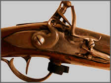
The flintlock overcame a problem that dated back to the time of early firearms. The small but critical improvement that separates the flintlock from the snaphaunce is the frizzen. This device combines the functions of a priming pan cover and an anvil into a single unit. Compared to any previous pan-cover system, this simple improvement proved significant to the history of firearms technology. When ready for firing, the frizzen is in the down position, fully covering the priming charge in the pan. When the cock falls, the flint strikes the curved anvil portion of the frizzen, producing the required sparks. Like the snaphaunce, the frizzen pushes up and opens the pan cover, allowing the sparks to fall into the priming charge.
The flintlock allowed the soldier or hunter to carry arms that were truly ready for action at a moments notice. The weapon was relatively safe yet required only that the user raise and cock it before taking the shot. No one had to remember to open a pan cover. The frizzen was not completely waterproof; it could not protect the priming charge against heavy rain or submersion. However, it provided reasonable protection in light rain and eliminated the wind problem.
An evolutionary rather than a revolutionary change, the flintlock was relatively simple, inexpensive (in its basic form), and well suited to military use. The French issued their first true flintlock military arms in 1717 and retained the basic pattern until 1842. The story was similar in other countries; the flintlock reigned on the battlefield for at least a century. New developments in the sporting arms field would ultimately supplant flint ignition and lead to the cartridge firearm.
Chemical Ignition
The flintlock and all of its predecessors had an external pan that held the priming charge in a position where sparks (or the match in primitive arms) could reach the charge. The vent was a required feature yet left a hole in the combustion area of the barrel. After the flame from the priming charge ignited the main charge, gases and other combustion by-products would escape through the vent. This reduced the amount of gas available to push the projectile, allowed moisture into the main charge, and exposed the shooter and those nearby to particulate residue that could injure eyes and skin. Combined with the fragile nature of pan priming, the vent forced a technology leap to achieve a military weapon that could handle a wider range of environmental conditions and more efficiently use the propellants stored energy.
Modern firearm barrels are tubes open at both ends except when ready for firing. Chemical ignition led to the development of designs for temporarily sealing one end of the barrel.
Chemical initiation overcame the problem of waterproofing and improved the speed and ease of loading. Chemical initiators for cartridges are percussion-sensitive compounds or mixtures of materials. Alone, these mixtures will not produce sufficient heat or sparks for igniting propellants, but will do so in combination.
The first widely used chemical initiators contained mercury fulminate or potassium chlorate in combination with oxidizers. As a group, these mixtures were called fulminating powders. Although knowledge of their properties dates to the beginning of the eighteenth century, their full benefits for firearm ignition were not realized until 1793. A Scottish Presbyterian minister, the Reverend Alexander John Forsyth (1768-1843), was an avid hunter, enjoyed repairing firearms, and dabbled in chemistry. He began experimenting in 1793 with pellets of fulminating powder placed on a tube that could be struck by the firearms hammer. The fulminate exploded, and its flame passed through the tube into the main propellant charge. History credits Forsyth with fabricating the first gunlock to use fulminating powder around 1812.
Forsyth continued to work with fulminate pellets. His lock systems evolved into a pivoting magazine holding multiple pellets that fell on the ignition tube as the magazine was rotated. The Forsyth system was used in high-grade sporting arms, but was considered too expensive and delicate for widespread military application.
A number of inventors saw the usefulness of fulminate for firearm ignition. A variety of fulminate holders were used, including tapes containing multiple pellets (nearly identical to toy gun roll caps), discs, and tubes. Tubes containing fulminate were an invention of noted British gun maker Joseph Manton. They were about 5/8" in length and were installed for each shot at a right angle to the bore in flint-fired arms (in a location roughly corresponding to the vent). The hammer struck the side of the tube, igniting the fulminate and subsequently the main charge.
Percussion Cap
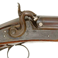
The ultimate victor in the battle for external chemical priming was the percussion cap. Original caps (circa 1814) were small, soft iron cups with fulminate in the bottom. Later, pewter and soft copper were used for the cups.
To use percussion caps, a firearm required three basic modifications from a classic flintlock. First, an enlarged hollow projection (called the drum or bolster) had to be installed near the vent hole and pan. In most firearms, the drum is integrated with the barrel. Some are fitted with an access port that can be removed to allow for thorough cleaning. The internal passage in the drum typically starts at right angles to the bore and then turns 90 to the rear and approximately 45 upward to meet the hammer.
The second modification was a removable, replaceable tapered tube (nipple) which screwed into the drum and held the percussion cap. Nipples take direct blows from the hammer and are subjected to high heat and pressure. The tapering of the nipple allowed a snug-fitting cap, keeping it in place during routine gun handling.
The third modification was the transition from the cock to the hammer. The flint clamp was replaced by a one-piece hammer with a nose fitted to directly contact the rear face of the nipple. The surface that contacted the nipple was flat and typically surrounded by extra metal in the form of a skirt, which improved the degree of sealing provided by the percussion system.
These modifications overcame most of the problems of earlier firearm ignition systems. The percussion cap contributed to the sealing of the breech end of the barrel, improving ballistic performance and weatherproofing.
Once a percussion cap was fit onto the nipple, a blow of the hammer would snug the cap even tighter. This could make the spent cap difficult to remove. To counter this effect, some of the sealing properties of the cap were sacrificed. The sidewalls of the percussion cap were ribbed or folded to force the cap to split on firing. This loosened the spent cap on the nipple; little if any effort was required to extract a spent cap. Many simply fell away when the pressure of the hammer was removed.
At this point, improvements to chemical ignition required changes to both arms and ammunition to move the initiator inside the firearm. As will be discussed in the ammunition section, this resulted in a cartridge containing all the components of ammunition projectile, powder, and primer.
Additional Online Courses
- What Every First Responding Officer Should Know About DNA Evidence
- Collecting DNA Evidence at Property Crime Scenes
- DNA – A Prosecutor’s Practice Notebook
- Crime Scene and DNA Basics
- Laboratory Safety Programs
- DNA Amplification
- Population Genetics and Statistics
- Non-STR DNA Markers: SNPs, Y-STRs, LCN and mtDNA
- Firearms Examiner Training
- Forensic DNA Education for Law Enforcement Decisionmakers
- What Every Investigator and Evidence Technician Should Know About DNA Evidence
- Principles of Forensic DNA for Officers of the Court
- Law 101: Legal Guide for the Forensic Expert
- Laboratory Orientation and Testing of Body Fluids and Tissues
- DNA Extraction and Quantitation
- STR Data Analysis and Interpretation
- Communication Skills, Report Writing, and Courtroom Testimony
- Español for Law Enforcement
- Amplified DNA Product Separation for Forensic Analysts


