Home | Glossary | Resources | Help | Contact Us | Course Map
Archival Notice
This is an archive page that is no longer being updated. It may contain outdated information and links may no longer function as originally intended.
Measuring Impressions
Most general rifling characteristics can be readily observed using the naked eye. However, the determination of the dimensions (width) of land and groove impressions presents additional considerations.
These considerations include the following:
- The widths of the land and groove impressions are small and must be accurately measured.
- A discipline-wide technique must be used to ensure reproducibility of results to compare against a standard.
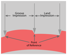
For measurement accuracy and reproducibility, reference points that are common to all bullets fired from conventionally rifled barrels must be established. These reference points define the location at which a land impression meets a groove impression. The width of the land impression is the width of the floor; the plateau and both adjacent slopes define the width of the groove impression.
Techniques
Measurements may be taken by a number of techniques. Regardless of the microscopic technique, the reference points must simultaneously be in focus; the slightly rounded surface between them may be slightly out of focus.
Land and groove impressions on damaged bullets may not be visible and/or measurable (useable). While it may not be necessary to take all measurements, it is important to take reliable measurements.
Examiners notes should reflect
- number of visible land and groove impressions,
- number of measurable land and groove impressions,
- measurements of useable land and groove impressions,
- measurements expressed to the nearest thousandth of an inch.
Dashed lines indicate damaged impressions; reliable measurements could not be taken.
| Example | ||||||
| As an example, the results accumulated around the circumference of a 380 Auto caliber bullet could be included in a worksheet as: | ||||||
| Land width dimensions/Land impressions | 118 | 121 | 119 | --- | 121 | --- |
| Groove width dimensions/Groove impressions | 138 | 142 | --- | 139 | 141 | 140 |
Equipment
Using a comparison or stereomicroscope, land and groove impressions can be measured using a variety of equipment:
- Micrometer
- Calipers
- Glass measuring reticule
- Electronic reticule
- Digital measuring equipment and software
- MP 6 optical projector (no microscope)
- Machinists scale
Descriptions of each of the above equipment can be found in Module 7.
A technique used by many examiners for measuring the widths of land and groove impressions is the air gap method. This technique is fast and accurate, requiring only a calibrated microscope and a micrometer. Calipers can be substituted for the micrometer.
Additional Online Courses
- What Every First Responding Officer Should Know About DNA Evidence
- Collecting DNA Evidence at Property Crime Scenes
- DNA – A Prosecutor’s Practice Notebook
- Crime Scene and DNA Basics
- Laboratory Safety Programs
- DNA Amplification
- Population Genetics and Statistics
- Non-STR DNA Markers: SNPs, Y-STRs, LCN and mtDNA
- Firearms Examiner Training
- Forensic DNA Education for Law Enforcement Decisionmakers
- What Every Investigator and Evidence Technician Should Know About DNA Evidence
- Principles of Forensic DNA for Officers of the Court
- Law 101: Legal Guide for the Forensic Expert
- Laboratory Orientation and Testing of Body Fluids and Tissues
- DNA Extraction and Quantitation
- STR Data Analysis and Interpretation
- Communication Skills, Report Writing, and Courtroom Testimony
- Español for Law Enforcement
- Amplified DNA Product Separation for Forensic Analysts


